
Products
LEO 32SWP3.6-23-1.5L/QG Sewage Grinding Pump
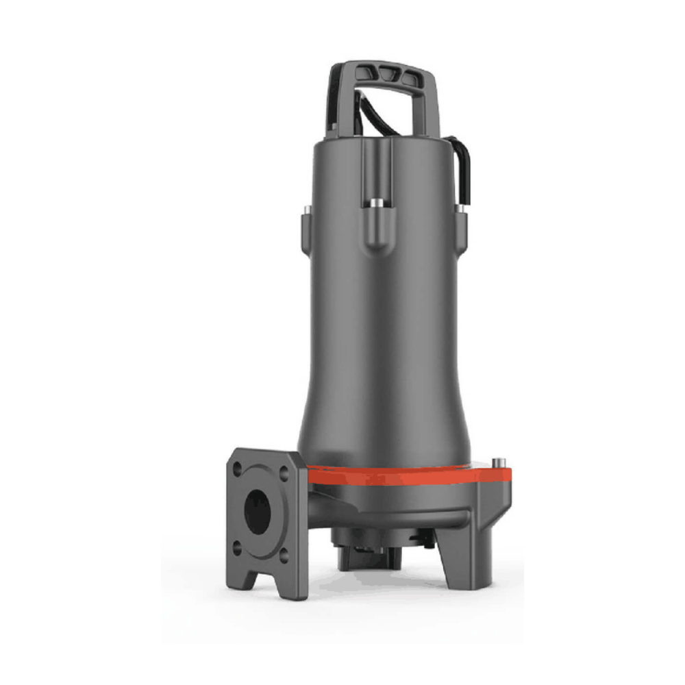
1.5 kW 3-phase 50 Hz sewage grinding pump; individual reference curve and exact product dimensions. Source conflicts flagged; supplied duty/version confirmation required.
LEO 32SWP3.6-23-1.5L/QG sewage grinding pump
Semi-open vortex impeller with cutting/grinding system for pressure sewage transfer. The product photograph is a representative manufacturer image for the 32SWP design family, not a guarantee of the exact supplied motor-stack length or accessories.
Published technical specifications
| Power | 1.5 kW / 2 HP |
|---|---|
| Phase / frequency / poles | 3-phase / 50 Hz / 2 poles; voltage requires supplied-nameplate confirmation. |
| Nominal discharge | 32 mm (1¼ inch); confirm interface. |
| Rated duty, published table | Q=3.6 m³/h at H=23 m |
| Separate maximum flow / head, published table | 10 m³/h / 23.2 m |
| Liquid temperature / pH | 0–40°C / pH 4–10 |
| Cable length reference | 10 m |
| Insulation / protection | Class F / IP68 |
| Maximum immersion | Unresolved: 5 m manufacturer/European reference versus 10 m local sheet. Do not assume 10 m; confirm supplied instructions. |
| Float switch | Not promised as standard for this version. |
Individual hydraulic reference and dimensions
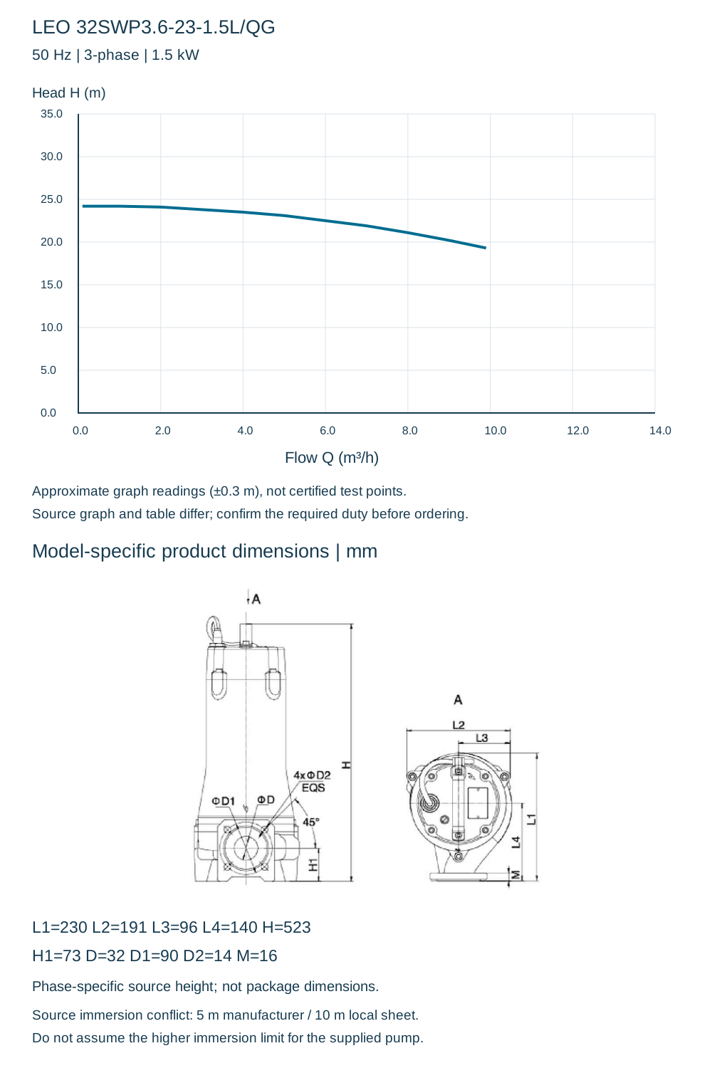
| Approx. flow Q (m³/h) | 0.1 | 1 | 2 | 3 | 4 | 5 | 6 | 7 | 8 | 9 | 9.9 |
|---|---|---|---|---|---|---|---|---|---|---|---|
| Approx. head H (m) | 24.2 | 24.2 | 24.1 | 23.8 | 23.5 | 23.1 | 22.5 | 21.9 | 21.1 | 20.2 | 19.3 |
| L1 | 230 mm |
|---|---|
| L2 | 191 mm |
| L3 | 96 mm |
| L4 | 140 mm |
| H | 523 mm |
| H1 | 73 mm |
| D | 32 mm |
| D1 | 90 mm |
| D2 | 14 mm |
| M | 16 mm |
Source conflicts and installation checks
The manufacturer graph and technical table disagree on parts of the performance envelope. The chart below reproduces approximate graph readings; the separate rated and maximum values retain the published numerical table without blending the two. Neither is independently confirmed. Request a selection against the actual duty and supplied version before ordering. Maximum flow and maximum head are separate limits, not one duty point. The graph also prints “7” at the evenly spaced 8 m³/h tick; flow calibration uses the consistent axis spacing and l/min scale, not that apparent label error.
No zero-head endpoint or extrapolated performance has been invented. Confirm cable, voltage, phase, operating immersion, duty point, elbow/flange and installation clearances before purchase. The grinding system does not establish a verified solids-passage diameter.