
Products
LEO 50SWE15-20-2.2L Submersible Sewage Pump
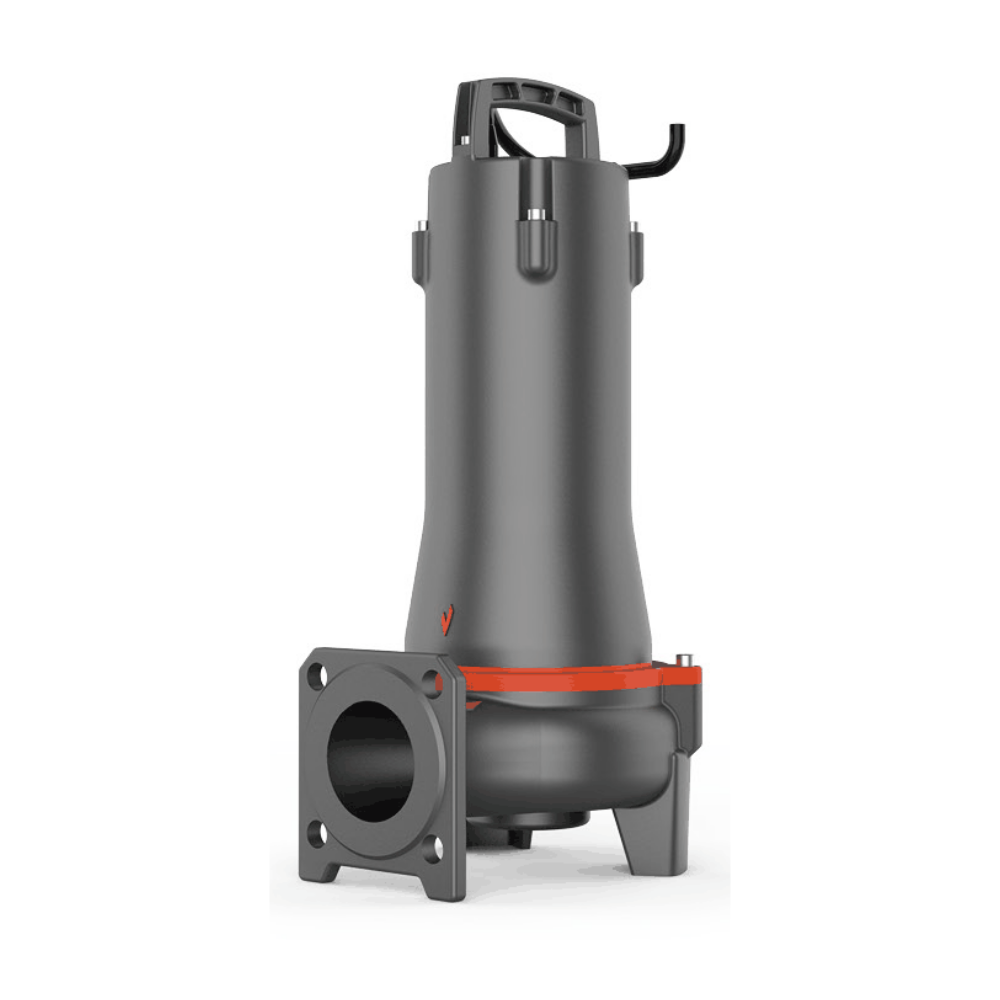
2.2 kW 3-phase 50 Hz sewage pump; model-specific dimensions and source-based hydraulic reference. Source conflicts flagged; supplied duty/version confirmation required.
LEO 50SWE15-20-2.2L submersible sewage pump
Enclosed channel impeller for wastewater drainage and suitable sewage-transfer duties. Manufacturer photograph represents the 50SWE design family; exact motor-stack length and supplied accessories may vary.
Published technical specifications
| Power | 2.2 kW / 3 HP |
|---|---|
| Phase / frequency / poles | 3-phase / 50 Hz / 2 poles; confirm voltage from supplied nameplate. |
| Nominal discharge | 50 mm; confirm elbow/coupling interface. |
| Rated duty, source table | Q=15 m³/h at H=20 m |
| Separate maximum flow / head, source table | 45 m³/h / 23 m |
| Maximum solids diameter, source table | 25 mm |
| Liquid temperature / pH | 0–40°C / pH 4–10 |
| Immersion limit | 5 m European versus 10 m local sheet: unresolved, confirm supplied instructions and do not assume higher limit. |
| Cable reference | 10 m |
| Insulation / protection | Class F / IP68 |
| Float switch | Not promised as standard for this version. |
Individual hydraulic reference and dimensions
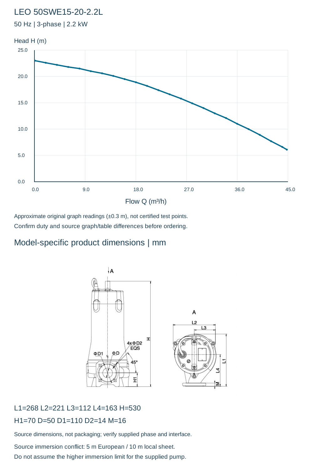
| Approx. Q (m³/h) | 0.1 | 2 | 4 | 6 | 8 | 10 | 12 | 14 | 16 | 18 | 20 | 22 | 24 | 26 | 28 | 30 | 32 | 34 | 36 | 38 | 40 | 42 | 44 | 44.8 |
|---|---|---|---|---|---|---|---|---|---|---|---|---|---|---|---|---|---|---|---|---|---|---|---|---|
| Approx. H (m) | 23 | 22.6 | 22.2 | 21.8 | 21.5 | 21 | 20.6 | 20.1 | 19.5 | 18.9 | 18.2 | 17.4 | 16.6 | 15.8 | 14.9 | 14 | 13 | 12.1 | 11 | 10 | 8.9 | 7.7 | 6.6 | 6.1 |
| L1 | 268 mm |
|---|---|
| L2 | 221 mm |
| L3 | 112 mm |
| L4 | 163 mm |
| H | 530 mm |
| H1 | 70 mm |
| D | 50 mm |
| D1 | 110 mm |
| D2 | 14 mm |
| M | 16 mm |
Source conflicts and installation checks
Manufacturer graph readings are approximate references (about ±0.3 m reading uncertainty), not certified test points or an acceptance tolerance. Published rated/max values remain separate; several graph/table envelope values differ. Maximum flow and head are separate limits, not one operating point. No extrapolated zero-head or shut-off endpoint is invented. Confirm supplied voltage, actual phase-specific height, cable, elbow/coupling, duty point and installation clearances. Do not substitute nominal discharge for the drawing dimension D.