
Products
LEO 50SWP10-10-1.1L/QG Sewage Grinding Pump
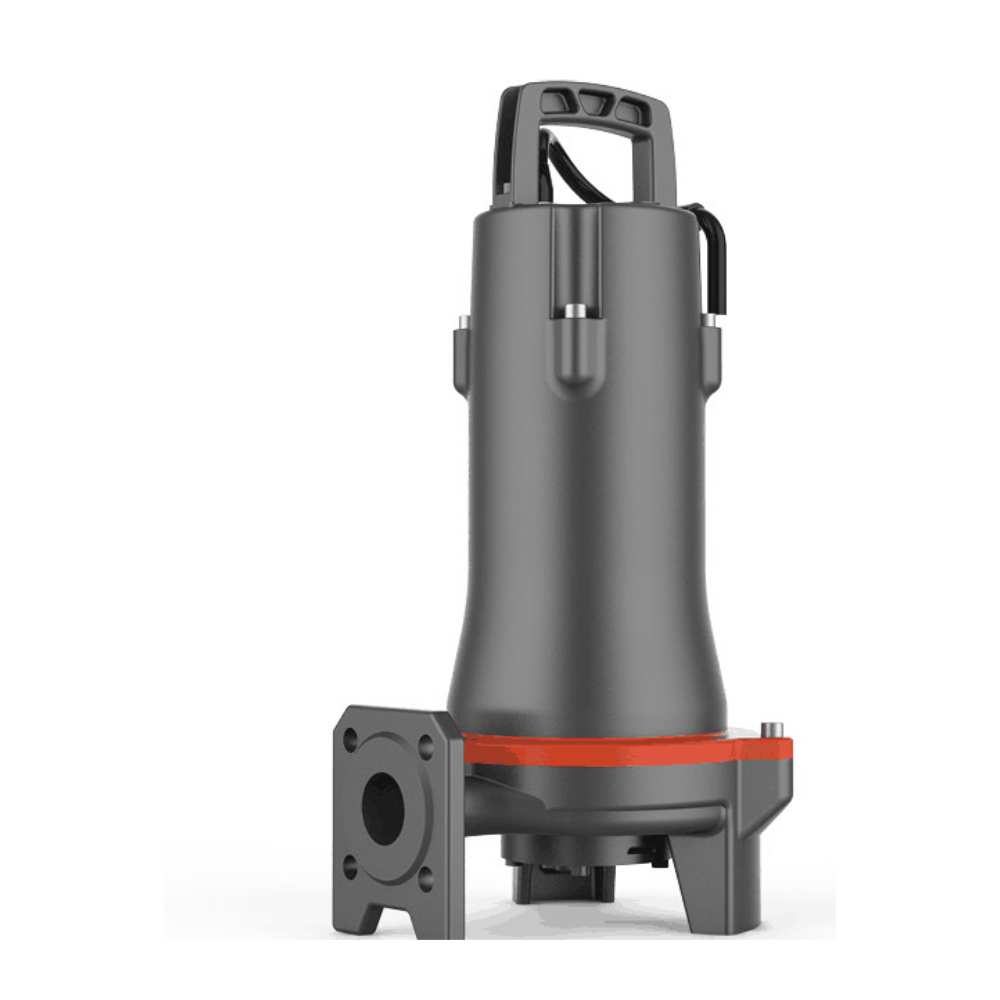
1.1 kW 3-phase 50 Hz sewage grinding pump; individual reference curve and exact product dimensions. Source conflicts flagged; supplied duty/version confirmation required.
LEO 50SWP10-10-1.1L/QG sewage grinding pump
Semi-open vortex impeller with cutting/grinding system for pressure sewage transfer. The product photograph is a representative manufacturer image for the 50SWP design family, not a guarantee of the exact supplied motor-stack length or accessories.
Published technical specifications
| Power | 1.1 kW / 1.5 HP |
|---|---|
| Phase / frequency / poles | 3-phase / 50 Hz / 2 poles; voltage requires supplied-nameplate confirmation. |
| Nominal discharge | 50 mm (2 inch); confirm interface. |
| Rated duty, published table | Q=10 m³/h at H=10 m |
| Separate maximum flow / head, published table | 20.5 m³/h / 17.5 m |
| Liquid temperature / pH | 0–40°C / pH 4–10 |
| Cable length reference | 10 m |
| Insulation / protection | Class F / IP68 |
| Maximum immersion | Unresolved: 5 m manufacturer/European reference versus 10 m local sheet. Do not assume 10 m; confirm supplied instructions. |
| Float switch | Not promised as standard for this version. |
Individual hydraulic reference and dimensions
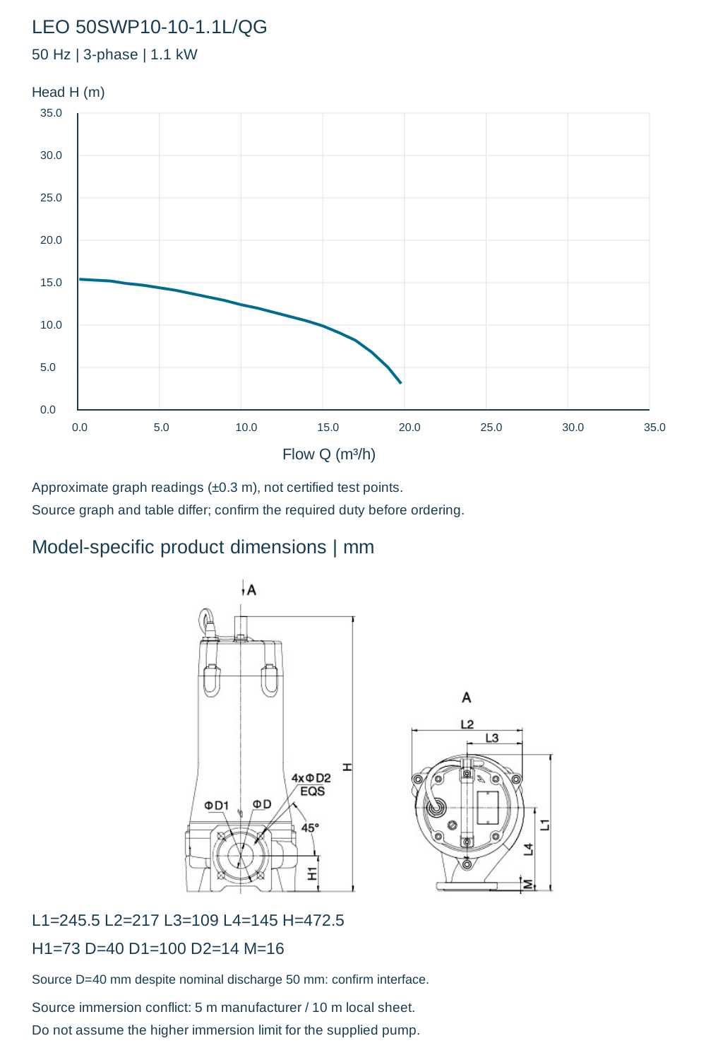
| Approx. flow Q (m³/h) | 0.1 | 1 | 2 | 3 | 4 | 5 | 6 | 7 | 8 | 9 | 10 | 11 | 12 | 13 | 14 | 15 | 16 | 17 | 18 | 19 | 19.8 |
|---|---|---|---|---|---|---|---|---|---|---|---|---|---|---|---|---|---|---|---|---|---|
| Approx. head H (m) | 15.4 | 15.3 | 15.2 | 14.9 | 14.7 | 14.4 | 14.1 | 13.7 | 13.3 | 12.9 | 12.4 | 12 | 11.5 | 11 | 10.5 | 9.9 | 9.1 | 8.2 | 6.8 | 5 | 3.1 |
| L1 | 245.5 mm |
|---|---|
| L2 | 217 mm |
| L3 | 109 mm |
| L4 | 145 mm |
| H | 472.5 mm |
| H1 | 73 mm |
| D | 40 mm |
| D1 | 100 mm |
| D2 | 14 mm |
| M | 16 mm |
Source conflicts and installation checks
The manufacturer graph and technical table disagree on parts of the performance envelope. The chart below reproduces approximate graph readings; the separate rated and maximum values retain the published numerical table without blending the two. Neither is independently confirmed. Request a selection against the actual duty and supplied version before ordering. Maximum flow and maximum head are separate limits, not one duty point. The dimension table prints D=40 mm although nominal discharge is 50 mm (2 inch); confirm the actual flange/elbow interface and do not fabricate from nominal size alone.
No zero-head endpoint or extrapolated performance has been invented. Confirm cable, voltage, phase, operating immersion, duty point, elbow/flange and installation clearances before purchase. The grinding system does not establish a verified solids-passage diameter.