
Products
LEO LRP36-80F/200
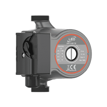
LEO LRP36-80F/200. Model selection, price and availability on enquiry.
LEO LRP36-80F/200
Model in the LRP Hot Water Circulation Pump Range.
50 Hz reference specifications
For heating and HVAC water circulation. Confirm liquid compatibility and any potable-water approval requirements before selection. These values reproduce LEO's published European 50 Hz sheet; confirm the supplied version and required duty before ordering.
| Item | Published reference |
|---|---|
| Electrical supply | 220–240 V / 50 Hz |
| Motor control | Three speed settings (3 / 2 / 1) |
| Insulation / enclosure | Class H / IP44 |
| Liquid temperature | 2–110 °C |
| Body / connection | Cast-iron body, flange-connection version (F). |
Published speed ratings — LRP36-80F/200
| Speed | Electrical power (W) | Maximum flow (L/min) | Maximum head (m) |
|---|---|---|---|
| 3 | 270 | 170 | 7.3 |
| 2 | 245 | 113 | 6.7 |
| 1 | 160 | 65 | 5.4 |
Maximum flow and maximum head are separate limits, not a simultaneous operating point. They have not been joined to invent a performance curve.
Locally published hydraulic curve and dimensions
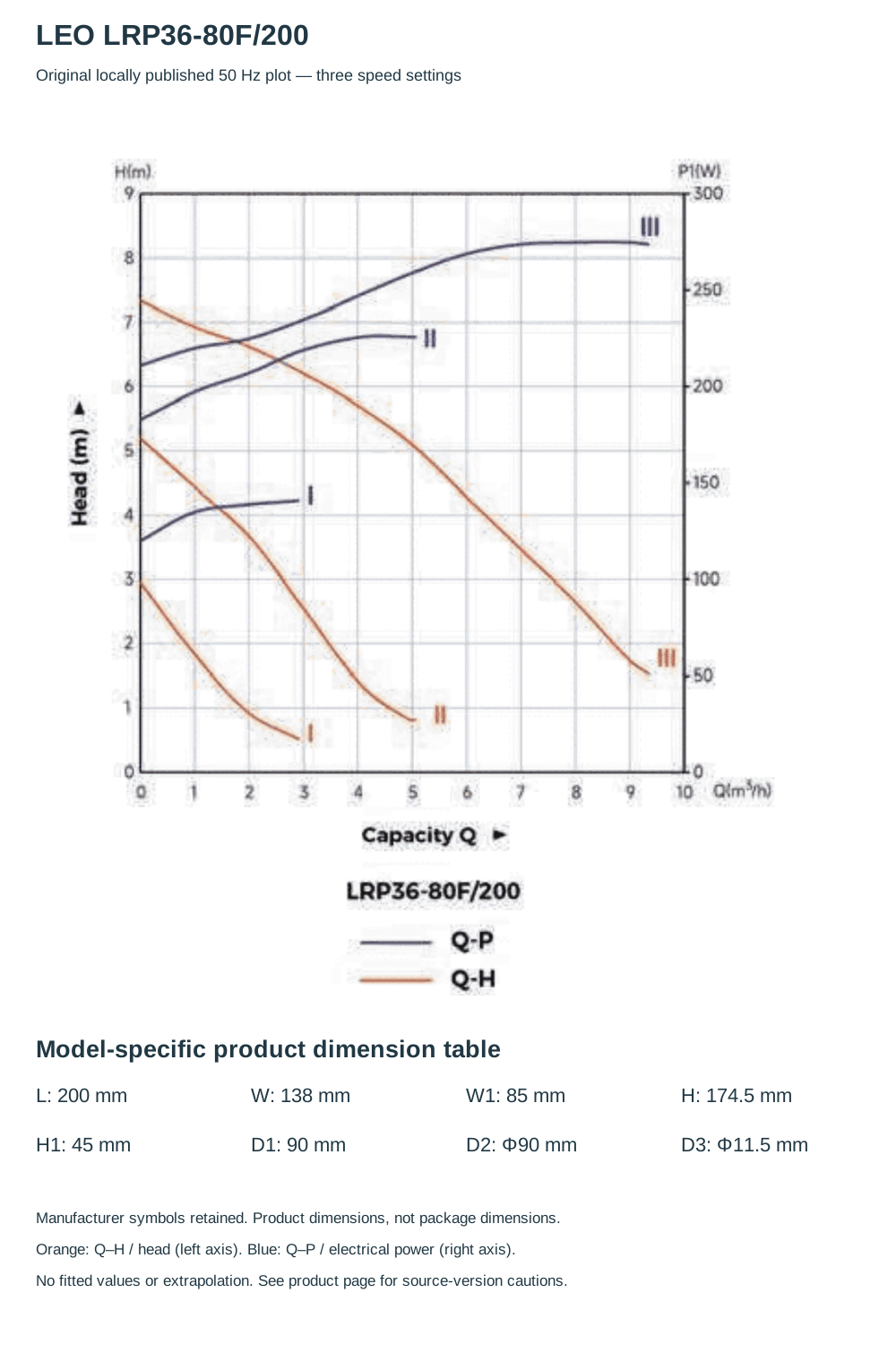
The locally published LEO 50 Hz sheet explicitly identifies LRP36-80F/200 in its technical and dimension tables and hydraulic-plot legend. The original plot is reproduced without fitted numerical points or extrapolation. Orange Q–H curves use the left head axis; blue Q–P curves use the right electrical-power axis.
Locally published ratings — LRP36-80F/200
| Setting | Electrical power (W) | Current (A) | Maximum flow (m³/h) | Maximum head (m) |
|---|---|---|---|---|
| 3 | 270 | 1.2 | 10.2 | 7.3 |
| 2 | 245 | 1.1 | 6.8 | 6.7 |
| 1 | 160 | 0.72 | 3.9 | 5.4 |
The European reference table above is a separately identified publication. The local graph and table can still show different intercept/maxima; confirm the supplied version and accepted duty. Local dimension symbols W/W1 correspond to the values displayed as B/B1 in the European reference. No ambiguous non-F curve has been substituted.
Product dimensional data
| Drawing symbol | Model value |
|---|---|
| L | 200 mm |
| B | 138 mm |
| B1 | 85 mm |
| H | 174.5 mm |
| H1 | 45 mm |
| D1 | 90 mm |
| D2 | Φ90 mm |
| D3 | Φ11.5 mm |
Symbols follow the manufacturer dimension drawing. L is the installation length between connections. G is the thread callout, not a metric dimension or a guarantee of union accessories. D symbols apply to flanged versions. Package sizes have not been substituted for product dimensions.
Source-version and duty confirmation
The manufacturer's tabular speed maxima and drawn curve intercepts do not always agree. Both are reproduced as published rather than silently reconciled; the applicable supplied version and accepted duty point require confirmation.
Other LEO publications can give different maximum-flow/head figures for the same base model code. Confirm the nameplate and applicable technical sheet for the supplied unit.
Confirm the required flow, head, liquid conditions and electrical supply with Krächtig before ordering. Price and availability on enquiry.